In late 2012 I was asked to design a portable system able to scan human faces for border control. At that time The Microsoft Kinect was dominating the field of the 3D acquisition devices, and in a very short time they sold more than 2 million devices. Unfortunately Microsoft Kinect v1/v2 is not that friendly for very mobile applications, and more portable solutions, like project Tango, or sensor io were still in a sperimental stage. After 5 years the scene is totally different, with dozen of devices available. We were able to design an active stereo system composed of a mid-range smartphone, and a pico-projector, driven by an Android App that we wrote for the acquisition and 3D reconstruction. In Spring 2013 The CiTer approved our project with a grant, and we deliver the outcomes in Spring 2014 at the CiTer Spring meeting at SUNY BUffalo (NY). In that occasion we made a short demo about the device. In 2016 our work was published on the IEEE Sensor Journal.
Since the device was targeted for biometric, in particular border control, portability, battery powered, speed, and accuracy were the driven factors.
For these reasons we excluded techniques based on multi views stereo that were giving good results on static objects ICCV13.
We decided to use active scanning techniques, based on the illumination of the subject with structured light. Pretty well known are the work of Taubin at Brown University, and Song Zhang at Purdue.
However, if the smartphones camera were good enough, the main problem was to find a compact and portable light source.
Fortunately, a new kind of devices were starting to be available at reasonable price, and battery powered: the nano, pico, and micro projectors.
For our complete setup we decided to use an Android smartphone: a mid-range device Nexus 4 with Android JellyBean. Till Android Lollipop almost all the smartphone were capable to output the video signal from the charging port. After, with the advent of google chromecast they decided to exclude the video output, and now only a few devices can be connected through HDMI port.
However, right now there are smartphones and tablets with included pico projectors.
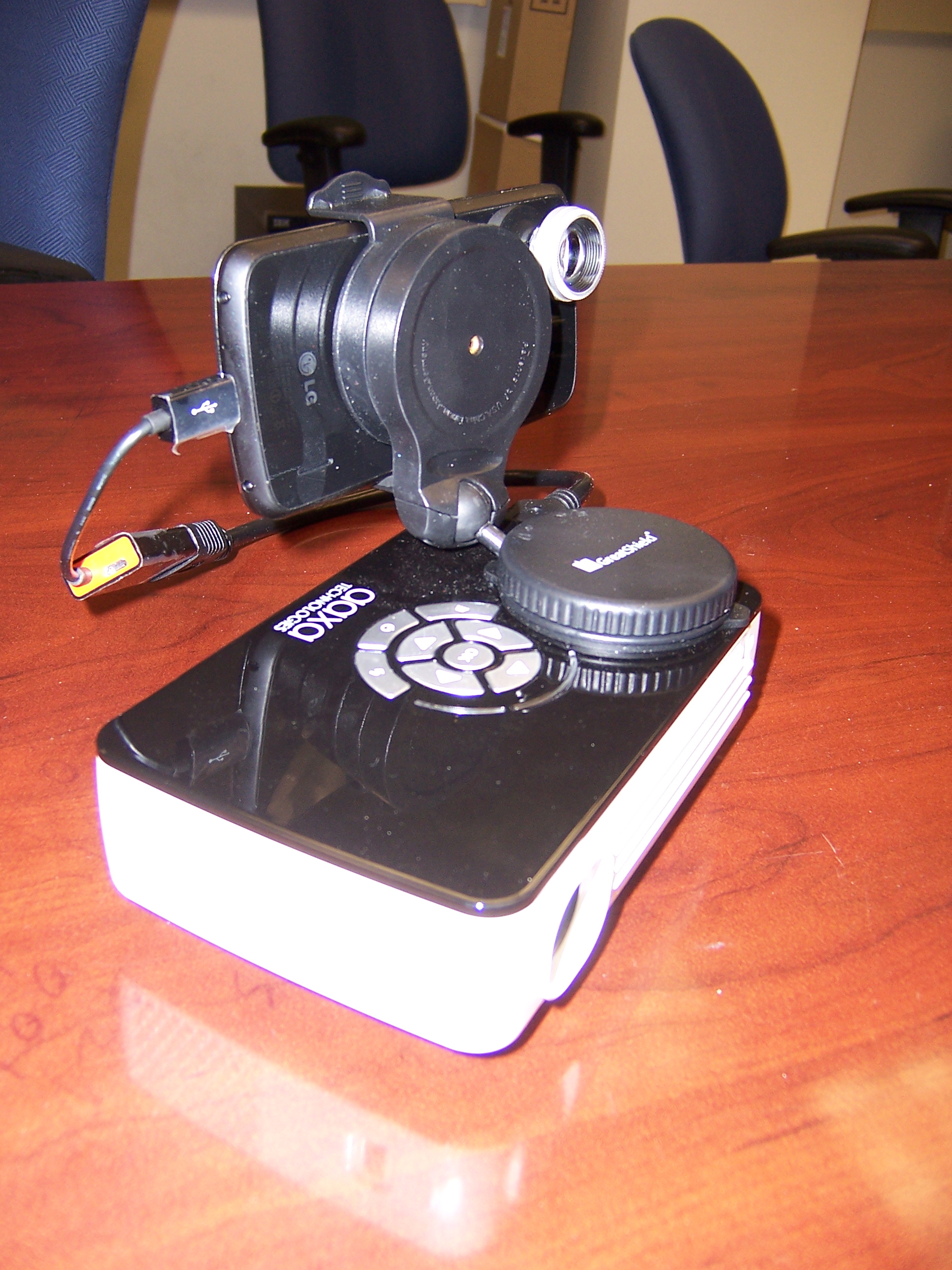
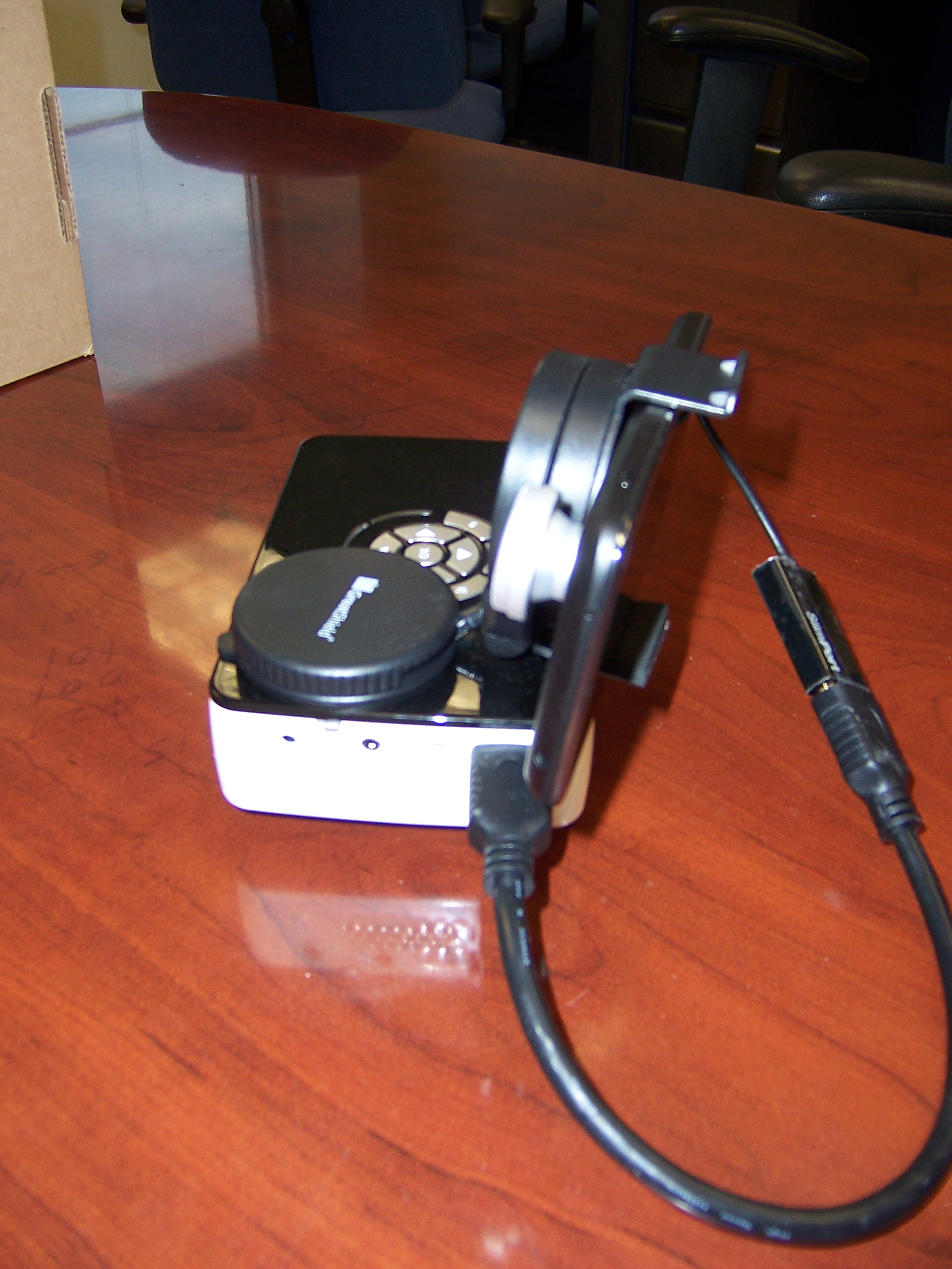
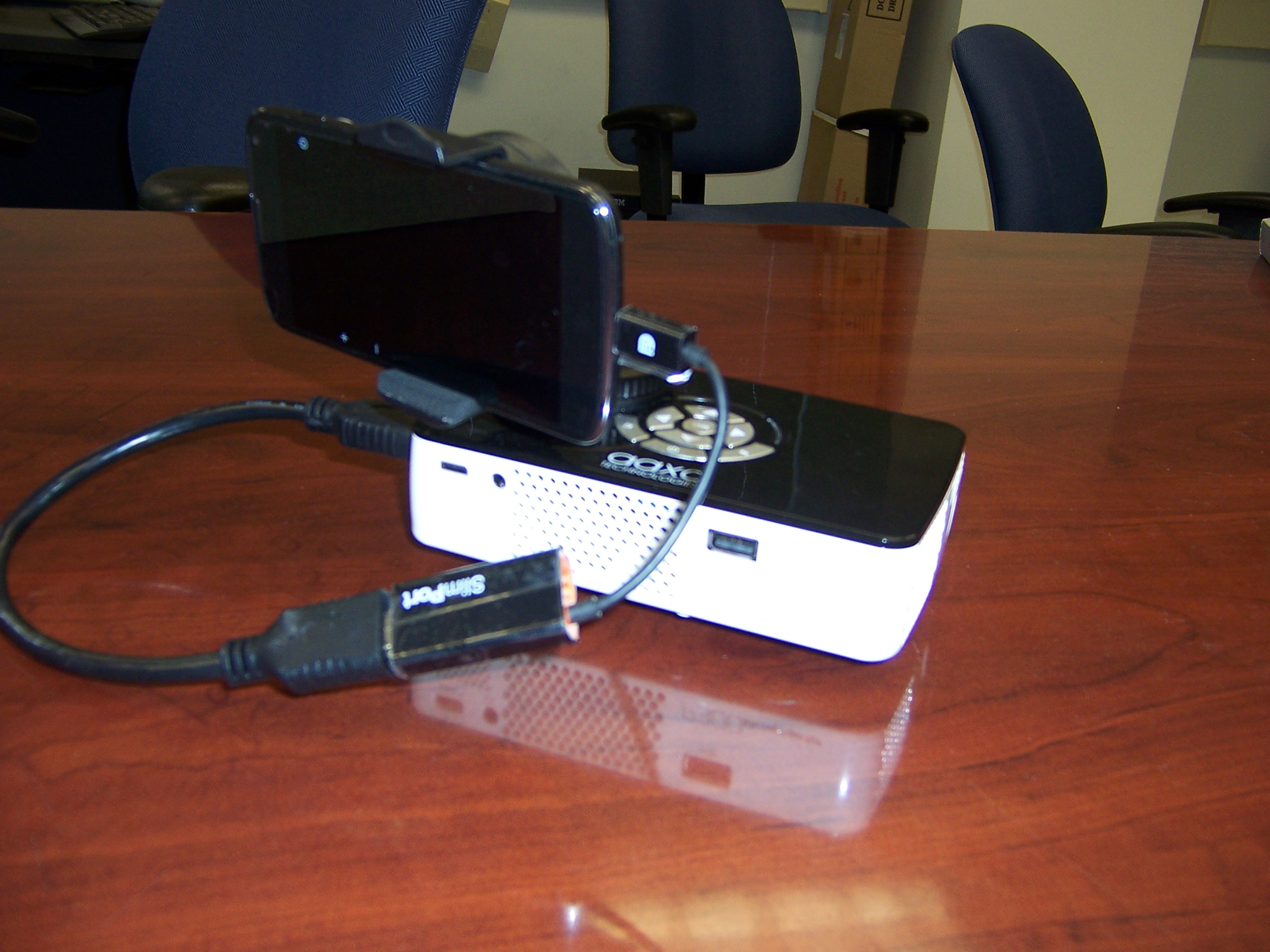
Our prototype in figure was composed of the Nexus 4, fixed to the micro-projector by a common car holder, and connected via HDMI cable. Since the light from the micro projector can be too bright for the eye we decided to use an additional tele lens to avoid to be too close to the subject.

The pico projector and the smartphone constitute an active stereo system, where, the pico projector substitute one of the camera in the stereo configuration. This configuration permits to use the basic stereo formulation, but it’s more robust since less affected by the external light, serious problem for the stereo matching reconstruction. As will see later, using fringe pattern with active stereo configuration, speed up the scan, then the 3D reconstruction. This solution, used by the majority of high precision 3D scanners present some downsides. The principal is the calibration procedure of the system.
The calibration of a camera lens is a very important step in 3D reconstruction, since other than the estimated ratio between the real and represented object, the lens introduce different distortions, making the reconstruction not accurate. With the calibration procedure we measure all the intrinsic and extrinsic quantities of the camera system, correcting distortions, and increasing the accuracy of the measures. Traditional monocular optics can be easily calibrated using simple algorithms that leverage the the knowledge of a given patterns and the relative representation on the focal plane in term of pixels. Common patterns are chessboards with black and white squares, thus easy to detect corners automatically. For a multi-views system, other than the intrinsic parameters of each lens, wwe need to measure the position, and orientation, respect to a reference, of the cameras. In the passive stereo, this is possible repeating the calibration procedure for each camera, then with the stereo registration of the two acquired images is possible to compute the extrinsic, and parallax parameters. In active stereo setup this procedure is quite hard, since the projector cannot " see " the pattern! The trick is to calibrate the camera first, then project the pattern with the projector and use the camera as a proxy. We refer to Moreno et. al. for a more extensive explanation and other references.
When I started to study structured light for 3D active acquisition devices I was literally astonished to find so many parallel, and the same math I was using a few years before in electrical communication. The same principle used in radar, sonar, and communication, is to transmit information shape from the source: object to scan to the receiver, the camera.
However, the object per se do not emit any information. What the human eye, or a camera see is the appearance, something that is difficult to describe.
Varphilosopher, neuroscientists, and also computer scientist have often discussed about it, and it’s still an hot topic.
To retrieve the shape information we have to sense the object. The information to acquire is in the form of x,y,z coordinate. Illuminating the subject with a light source, and receiving the distorted light with the camera is an analogous to radar, and sonar systems.
The difference is the frequency of the electromagnetic radiation used. Hundred, or thousand of MegaHertz in the case of the radar, 100 millions of Mhz for the visible light.
With different operating frequencies, although the same basic formulation, different noise and nuisances are playing a major role in the system performance.
There have been many structured light works using different patterns. A primitive, but simple and thoughtful is the work of Bouguet and Perona. They use a simple desk lamp, and by the object shadow is possible to reconstruct the shape.
However, the speed of the system is restricted by the camera frame rate, and the stick speed to create the shadow.
An extension to this principle is the use of more complex structured patterns. The literature is vast, and is quite hard to keep track of all the little contributions.
The three main typologies are: * binary coded light striping * gray/color coded light striping * phase Shifting.
The main difference regard the way the shape information is encoded. A more thorough explanation can be found here.
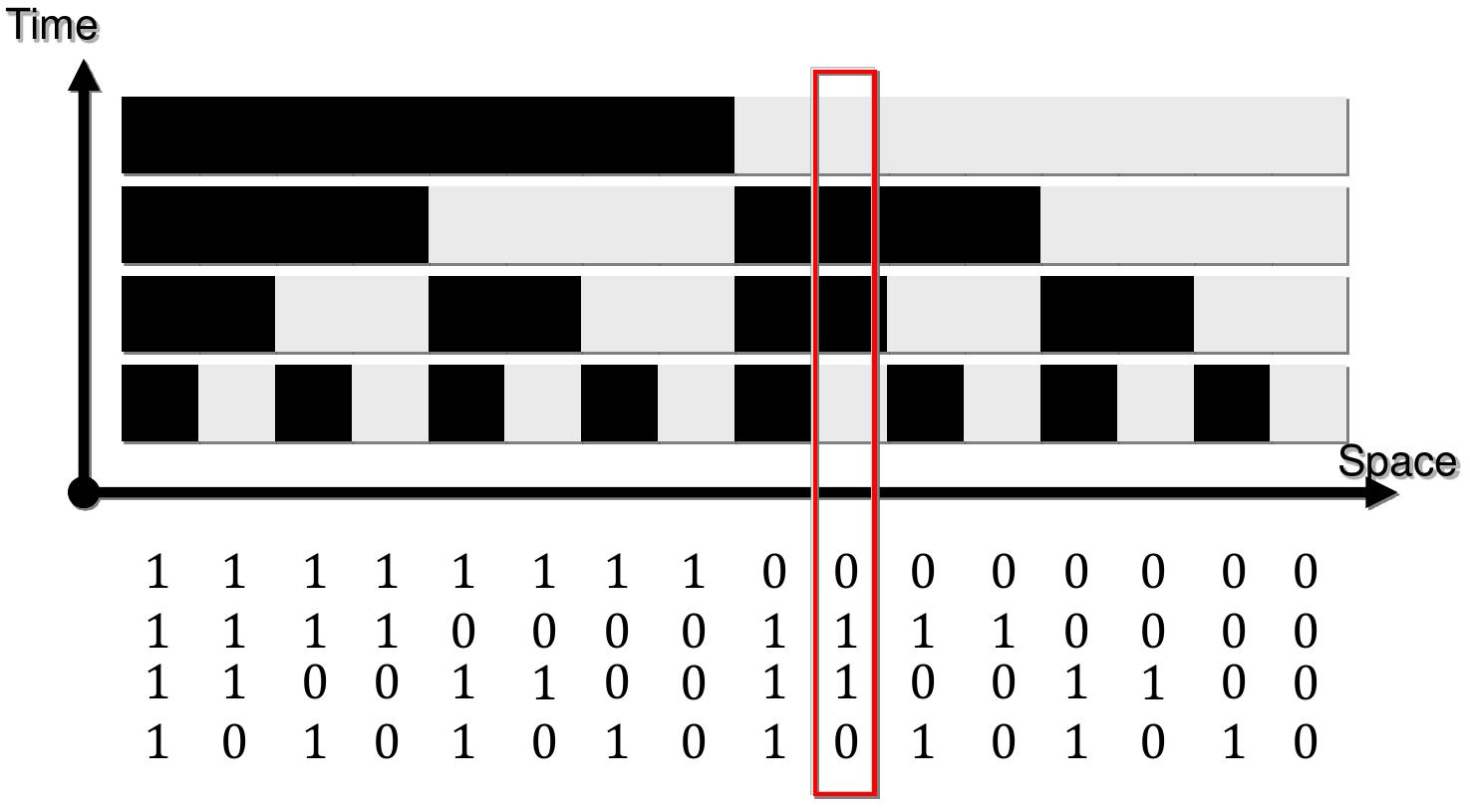
The first two techniques code the amplitude of the pattern light with discrete values. A set of patterns are successively projected onto the measuring surface, codeword for a given pixel is formed by a sequence of patterns. The main problem with this techniques is that the number of patterns is limited by the codeword length. Gray code can be used for robustness: adjacent stripes must only differ in 1 bit. However these techniques, used in old scanners, make the system slow, and especially are not resilient to external illumination, because the information is coded in the white or black level of the light.
A more interesting technique, introduced by Guehring et al
is the phase-shift PS method. The PS method projects a sequence of periodic intensity patterns, each of which is offset by a fraction of its period from the previous one, so that the entire period is covered. As a result, one obtains a so-called relative phase map, which is also of a periodic nature: values readily available from the relative wrapped phase map are said to be wrapped in the range modulo .
The PS method typically assumes a projection of periodic sinusoidal patterns several times, where a periodic sine pattern is shifted between projections. A periodic pattern is actually shifted N times by an amount of , where shifts are equally distributed to cover the entire period:
For a camera image pixel, the detected gray-level intensity, at position, obtained as a result of a projected periodic pattern in context and for a shift i can be modeled as:
where is the background intensity, is the amplitude modulation of fringes, is the spatial carrier frequency, is the phase modulation of fringes.
The above equation is very common in electrical communications! It’s the basic formulation used in modulation theory. In particular, the above form is called phase modulation, or angle modulation. This type of modulation is very interesting, since encode the information on phase variations. Common distortions of the electrical signal on means like coaxial cables, fiber optics, or ether are principally associated with the amplitude, encoding the information on the phase makes the system more resilient to noise. Moreover, since is discrete, the phase variations are discrete too. In electrical communications this modulation is called PSK: phase shift keying, used commonly to transmit digital signals.
My experience
As Ham Radio operator I used many many times the PSK for packet transmission. In early 2000 was able to meet and experimenting high speed packet transmission in Northern Italy and Slovenia where Matiaz Vidmar developed a BPSK radio at 2400 MHz.
Phase-shifting methods are extensively employed in optical metrology, especially with the development of digital computers and digital display technologies. A well known algorithm use just three phase shift. Three-step phase-shifting algorithm have the advantage of fast measurement because they require the minimum number of fringe images to reconstruct one 3D shape. Each shift has a variation of . The correspondent intensities of fringe images are:
To recover the realtive phase there is a closed form solution:
Due to the periodic nature of a given periodic pattern, value by itself is not a unique representative that we can use to solve the correspondence problem between the image pixels of two or more cameras, i.e., between a single camera and the source of projection, e.g. a common video projector.
The phase is called modulo at each pixel. If the fringe patterns contain multiple fringes, as often is the case, phase unwrapping is necessary to remove the sawtooth-like discontinuities and obtain a continuous phase map.
Some initial works on fringes used only one fringe containing the whole image. This technique lead to poor results due to the low resolution of the phase, or better said the degree/pixel ratio. Using more fringes we are able to have higher resolution, but with more fringes we have an increase of the computational complexity of the unwrapping algorithm.
A pattern period can be defined either directly by the number of requested periods that pattern must have, or by the length of a single period, bearing in mind the total available pattern width in the context.
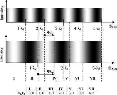
Figure shows the appearance of two sine patterns defined by integer length periods and : each pattern column has an intensity according to the sine value of its position on the abscissa axis, and the propagation of the absolute phase axis along the width of the pattern. A pair of relative phases , is indicated for the arbitrary absolute phase value and the following equations hold:
However, this method assume multiple patterns, and multiple acquisitions with different frequencies. Unfortunately, this could be a important downside due to the low frame rate of the mobile device.
In this project we considered a different unwrapping technique, also known as spatial unwrapping, instead of the one cited above, that is denominated frequency unwrapping. The main difference between the two techniques is the acquisition time. Spatial unwrapping use (x,y) relation on the picture frame to reconstruct the absolute phase, instead frequency unwrapping use additional fringe to construct the relation between the picture frame and the absolute phase. The last techniques need to acquire additional frames that will cost in terms of acquisition time. In our implementation, using this type of technique is not feasible due to the mobile nature of the device. Making every acquisition blurry due to the hand and subjects movements. In fact they need to stay still for the whole acquisition. Doing some math: at 30 fps, and using 3 phases, the acquisition will last ms. However, increasing the number of frames to 4 ms. These times are unfortunately high for a handheld device. Unfortunately we discover, as we’ll explain in major details in the next sections, that a smartphone is not the ideal device to grab and record frames.
As a side note: the smartphone used for this project is the Nexus 4! I think more recent devices will definitely obtain better performances.
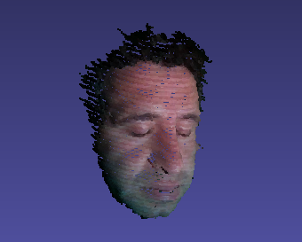
We used the Fast quality-guided flood-fill phase unwrapping algorithm for three-dimensional fringe pattern profilometry by Chen et. al. This algorithm present a good trade-off between speed, computatioanl complexity and results. As we’ll see later, not always perform well on human faces, and for this reason we modify it in a way we can correct the faulty reconstructions.
The proposed method consists of three steps. First, after the acquisition of the wrapped phase , a quality map is generated according to the phase variance adjacent pixels on the wrapped phase map. According to the quality map, the phase map is divided into several parts which are categorised as either rapid phase changing areas or smooth phase changing areas. Then quality-guided flood-fill phase unwrapping algorithm is applied to rapid phase changing areas and nonguided path-following algorithm is used in the smooth phase changing area. The proposed approach is much faster than the conventional non-guided path-following algorithm, and it is more robust than the non-guided path-following algorithm. Experiments are carried out to verify the performance.
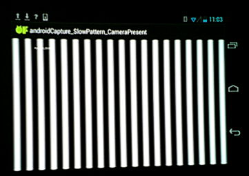
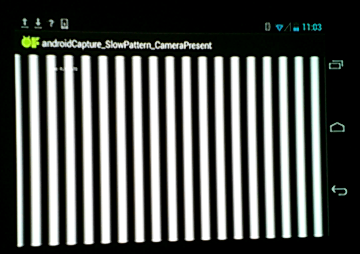
The following figures are obtained by our system projecting the patterns on a white projector screen. In the first row there are the three shifted patterns.
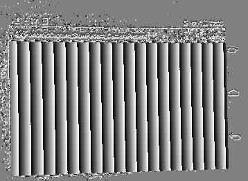


In the second row: the reconstructed wrapped phase on the left, an offset used by the unwrapping algorithm in center, and the final absolute phase on the right.
We used an unusual composition of tools and libraries to develop the software. Android SDK with the eclipse plugin was indispensable to create the apps, although painful and buggy at the time. Then we decided to use OpenFramework, an open source library in C++ for creative coding. We decided to use this combination because OpenFramework contained a version for Android with some function useful for our development. Developed in C++, to create Android Apps we used the Native Development Toolkit.In fact, the time we had to code everything and make a little in house acquisition was limited to one semester!! OpenFramework contains simple GUI, and portions of other useful libraries, like OpenCV, OpenGL ES, Point of Cloud library, and other useful utilities.
We developed initially three Android apps: calibration app, acquisition app, and reconstruction app. Later, we decided to include in a unique app the first two. Respective programs has been developed on PC too for correct some initials major bugs, and test the algorithms with a high resolution camera.
Despite a general shift towards remote cloud processing for a range of mobile applications, we argue that it is intrinsically desirable that heavy sensing tasks be carried out locally on-device, due to the usually tight latency requirements, and the prohibitively large data transmission requirement as dictated by the high Therefore we also demonstrate the feasibility of implementing and deploying the applications on mobile devices by showing low overhead for tasks like acquisition and 3D reconstruction, and more importantly visualization.
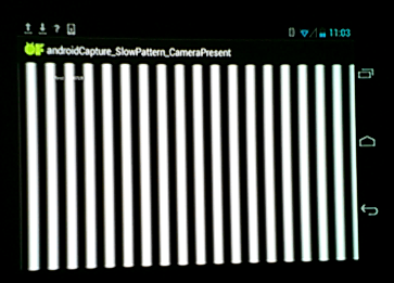
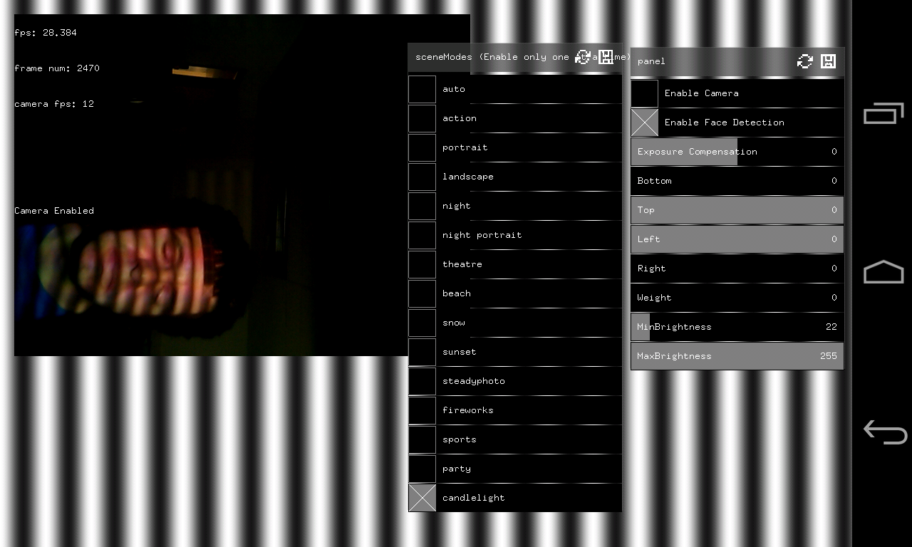
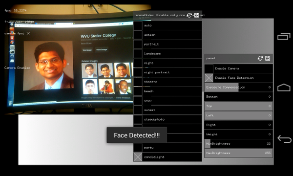
The main app, and also the most critical on a mobile deviceis the acquisition app. In fact, The acquisition is a temporized process, where the procedure is to simultaneously create and display the pattern, shoot with the camera, and store on memory the image.
The hardware is composed of a Nexus 4 smartphone running Android 4.4, a pico-projector, and usb to HDMI dongle. The pico-projector is battery powered and it can last one hour at full power. It’s able to acquire object at the distance of 2-3 meters on low light conditions, and 1-1.5 meters in normal light conditions..
 Marco Piccirilli